Tektronix MDO4054B-3, MDO4054B-3 Mixed Domain Oscilloscope, 500MHz, 4 Analogue. Ch.

Technical Document
Specifications
Brand
TektronixBandwidth
500MHz
Number of Analogue Channels
4
Interface
CAN, IIC, LIN, RS232, RS422, RS485, SPI, UART, USB
Sample Rate Random
2.5 Gsps
Screen Size
10.4in
Series
MDO4000B
Record Length
20M points/ch
Maximum Time Base
1000s/div
Safety Category
ANSI 61010-1-2004, CAN/CSA-C22.2 No. 61010.1: 2004, IEC 61010-1:2001, ISA 82.02.01, Low Voltage Directive 2006/95/EC and EN61010-1:2001, UL61010-1:2004
Rise Time
700ps
Display Type
Colour
Power Source
Mains
Maximum Vertical Sensitivity
10V/div
Length
147mm
Input Capacitance
3.9 pF
Dimensions
147 x 439 x 229mm
Minimum Time Base
1ns/div
Height
229mm
Input Impedance
1 MΩ
Minimum Vertical Sensitivity
1mV/div
Weight
5kg
Safety Category Level
CAT II
Safety Category Voltage
300V
Vertical Resolution
8 bit
Country of Origin
China
Product details
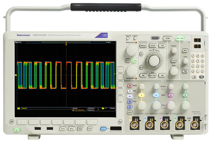
Tektronix Mixed Domain Oscilloscopes MDO4000B Series
Tektronix MDO4000 oscilloscopes are the first to come with a built-in spectrum analyzer. This enables capture of time-correlated analog, digital and RF signals for a complete system view of the device. Both the time and the frequency domain can be viewed in a single glance.
Standard accessories include: GPIB-to-USB adapter TEK-USB-488 ( 113-143 ); TPP0500B passive probe ( 797-3390 ) for <500 MHz models; TPP1000 passive probe ( 728-6759 ) for 1 GHz models; P6616 ( 728-6753 ) logic probe. Other recommended probes: TPP0502 ( 734-5016 ) passive probe; TPP0850 (734-5010 ) & P5100A ( 734-5013 ) high-voltage passive probes; TAP1500 ( 661-3286 ), TAP2500 ( 232-288 ) & TAP3500 ( 668-7155 ) active probes; TCP0030A ( 781-0807 ) & TCP0150 ( 661-3283 ) current probes; TDP0500 ( 661-3292 ), TDP1000 ( 668-7167 ) & TDP1500 ( 668-7161 ) differential probes; THDP0200 ( 752-7357 ), THDP0100 ( 752-7353 ), TMDP0200 ( 752-7366 ) & P5200A ( 734-5029 ) high-voltage differential probes. Application modules: DPO4AUDIO ( 727-6695 ); DPO4AUTO ( 728-6706 ); DPO4AUTOMAX ( 728-6709 ); DPO4COMP ( 728-6703 ); DPO4EMBD ( 728-6712 ); DPO4ENET ( 728-6734 ); DPO4USB ( 728-6715 ); DPO4PWR ( 728-6719 ); DPO4LMT ( 728-6731 ) & DPO4VID ( 728-6728 ).
Time-correlated analog, digital and RF signal acquisitions in a single instrument
Wave Inspector® controls provide easy navigation of time-correlated data from time and frequency domains
Amplitude, frequency and phase vs. time waveforms derived from RF input
Selectable spectrum time to discover and analyze RF changes over time, including changes on a stopped acquisition
Mixed-domain Analysis
Complex design issues can be resolved quickly and efficiently
Dedicated front-panel controls for commonly-performed tasks
Automated peak markers identify frequency and amplitude of spectrum peaks
Manual markers enable non-peak measurements
Trace types include Normal, Average, Max Hold, Min Hold
Detection types include +Peak, -Peak, Average, Sample
Spectogram display facilitates observation and insight into slowly-changing RF phenomena
Automated measurements include Channel Power, Adjacent Channel Power Ratio (ACPR), Occupied Bandwidth (OBW)
Trigger on RF power level
Triggered or Free Run spectral analysis
Spectral Analysis
Supplied with
1 passive voltage probe per analog channel, logic probe (x1) & accessory kit, accessory bag, front cover, N-to-BNC adapter, documentation CD, user manual, OpenChoice® desktop software, calibration certificate, power cord
Mixed Domain Oscilloscopes
P.O.A.
1
RS Components & Controls (I) Ltd
Distribution hub - B-89, Sector 67, Noida, Gautam Budh Nagar, (Uttar Pradesh), 201 301
P.O.A.
Stock information temporarily unavailable.
1
Stock information temporarily unavailable.
Technical Document
Specifications
Brand
TektronixBandwidth
500MHz
Number of Analogue Channels
4
Interface
CAN, IIC, LIN, RS232, RS422, RS485, SPI, UART, USB
Sample Rate Random
2.5 Gsps
Screen Size
10.4in
Series
MDO4000B
Record Length
20M points/ch
Maximum Time Base
1000s/div
Safety Category
ANSI 61010-1-2004, CAN/CSA-C22.2 No. 61010.1: 2004, IEC 61010-1:2001, ISA 82.02.01, Low Voltage Directive 2006/95/EC and EN61010-1:2001, UL61010-1:2004
Rise Time
700ps
Display Type
Colour
Power Source
Mains
Maximum Vertical Sensitivity
10V/div
Length
147mm
Input Capacitance
3.9 pF
Dimensions
147 x 439 x 229mm
Minimum Time Base
1ns/div
Height
229mm
Input Impedance
1 MΩ
Minimum Vertical Sensitivity
1mV/div
Weight
5kg
Safety Category Level
CAT II
Safety Category Voltage
300V
Vertical Resolution
8 bit
Country of Origin
China
Product details
Tektronix Mixed Domain Oscilloscopes MDO4000B Series
Tektronix MDO4000 oscilloscopes are the first to come with a built-in spectrum analyzer. This enables capture of time-correlated analog, digital and RF signals for a complete system view of the device. Both the time and the frequency domain can be viewed in a single glance.
Standard accessories include: GPIB-to-USB adapter TEK-USB-488 ( 113-143 ); TPP0500B passive probe ( 797-3390 ) for <500 MHz models; TPP1000 passive probe ( 728-6759 ) for 1 GHz models; P6616 ( 728-6753 ) logic probe. Other recommended probes: TPP0502 ( 734-5016 ) passive probe; TPP0850 (734-5010 ) & P5100A ( 734-5013 ) high-voltage passive probes; TAP1500 ( 661-3286 ), TAP2500 ( 232-288 ) & TAP3500 ( 668-7155 ) active probes; TCP0030A ( 781-0807 ) & TCP0150 ( 661-3283 ) current probes; TDP0500 ( 661-3292 ), TDP1000 ( 668-7167 ) & TDP1500 ( 668-7161 ) differential probes; THDP0200 ( 752-7357 ), THDP0100 ( 752-7353 ), TMDP0200 ( 752-7366 ) & P5200A ( 734-5029 ) high-voltage differential probes. Application modules: DPO4AUDIO ( 727-6695 ); DPO4AUTO ( 728-6706 ); DPO4AUTOMAX ( 728-6709 ); DPO4COMP ( 728-6703 ); DPO4EMBD ( 728-6712 ); DPO4ENET ( 728-6734 ); DPO4USB ( 728-6715 ); DPO4PWR ( 728-6719 ); DPO4LMT ( 728-6731 ) & DPO4VID ( 728-6728 ).
Time-correlated analog, digital and RF signal acquisitions in a single instrument
Wave Inspector® controls provide easy navigation of time-correlated data from time and frequency domains
Amplitude, frequency and phase vs. time waveforms derived from RF input
Selectable spectrum time to discover and analyze RF changes over time, including changes on a stopped acquisition
Mixed-domain Analysis
Complex design issues can be resolved quickly and efficiently
Dedicated front-panel controls for commonly-performed tasks
Automated peak markers identify frequency and amplitude of spectrum peaks
Manual markers enable non-peak measurements
Trace types include Normal, Average, Max Hold, Min Hold
Detection types include +Peak, -Peak, Average, Sample
Spectogram display facilitates observation and insight into slowly-changing RF phenomena
Automated measurements include Channel Power, Adjacent Channel Power Ratio (ACPR), Occupied Bandwidth (OBW)
Trigger on RF power level
Triggered or Free Run spectral analysis
Spectral Analysis
Supplied with
1 passive voltage probe per analog channel, logic probe (x1) & accessory kit, accessory bag, front cover, N-to-BNC adapter, documentation CD, user manual, OpenChoice® desktop software, calibration certificate, power cord
Mixed Domain Oscilloscopes