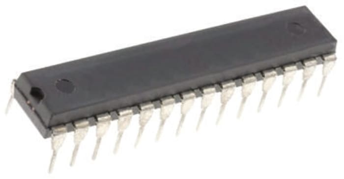
Microchip PIC18F2321-I/SP, 8bit PIC Microcontroller, PIC18F, 40MHz, 8 kB Flash, 28-Pin SPDIP

Technical Document
Specifications
Brand
MicrochipFamily Name
PIC18F
Package Type
SPDIP
Mounting Type
Through Hole
Pin Count
28
Device Core
PIC
Data Bus Width
8bit
Program Memory Size
8 kB
Maximum Frequency
40MHz
RAM Size
512 B
USB Channels
0
Number of PWM Units
2
Number of SPI Channels
1
Number of CAN Channels
0
Number of USART Channels
1
Number of UART Channels
1
Number of I2C Channels
1
Typical Operating Supply Voltage
2 → 5.5 V
Maximum Number of Ethernet Channels
0
Minimum Operating Temperature
-40 °C
Instruction Set Architecture
RISC
Number of ADC Units
1
Maximum Operating Temperature
+85 °C
Length
35.56mm
ADCs
10 x 10 bit
Height
3.81mm
Number of LIN Channels
0
Width
0.295in
Dimensions
1.4 x 0.295 x 0.15in
Pulse Width Modulation
2 (CCP)
Program Memory Type
Flash
Number of Ethernet Channels
0
Number of PCI Channels
0
Product details
PIC18F2221/2321/4221/4321 8-Bit Microcontrollers
The PIC18F Microcontrollers from Microchip are the most capable 8-bit devices within Microchip’s offer. Available within the range is CAN, LIN and Ethernet capability as part of a comprehensive range of peripherals to meet the needs of embedded applications and versions featuring XLP (Extreme Low-Power) Technology for where power consumption is a key consideration.
The PIC18F2221/2321/4221/4321 family of Microcontrollers is based upon Microchip’s PIC18 architecture offering a 31 level hardware stack and 77 instructions. These MCUs provide up to 10 MIPS, up to 8 Kbytes program memory with 512 bytes RAM and Data EEPROM of 256 bytes. On board is a configurable oscillator with ±1% accuracy.
Microcontroller Features
40 MHz Max. CPU Speed
77 Instructions
31 Level Hardware Stack
Configurable Internal Oscillator – Selectable Frequency Range 8 MHz to 31 kHz
25 I/O Pins – PIC18F2221/2321 Models
36 I/O Pins – PIC18F4221/4321 Models
nanoWatt XLP Technology
Power-On Reset (POR)
Power-Up Timer (PWRT)
Oscillator Start-Up Timer (OST)
Brown-Out Reset (BOR)
Extended Watchdog Timer (WDT)
Low-Voltage Programming (LVP)
In-Circuit Serial Programming (ICSP)
In-Circuit Debug (ICD)
Peripherals
10-bit Analogue to Digital Converter (ADC) – PIC18F2221/2321 10 Channels; PIC18F4221/4321 13 Channels
One Enhanced Capture, Compare, PWM Module – PIC18F4221/4321 Models Only
Capture, Compare, PWM Module – PIC18F2221/2321 x 2; PIC18F4221/4321 x 1
Two Comparators
One 8-bit Timers
Three 16-bit Timers
High/Low-Voltage Detection (HLVD) Module
Master Synchronous Serial Port (MSSP) Module with SPI and I2C
Enhanced Universal Synchronous Asynchronous Receiver Transmitter (EUSART)
Ideate. Create. Collaborate
JOIN FOR FREE
No hidden fees!


- Download and use our DesignSpark software for your PCB and 3D Mechanical designs
- View and contribute website content and forums
- Download 3D Models, Schematics and Footprints from more than a million products
P.O.A.
Each (In a Tube of 15) (Exc. GST)
15
RS Components & Controls (I) Ltd
Distribution hub - B-89, Sector 67, Noida, Gautam Budh Nagar, (Uttar Pradesh), 201 301

P.O.A.
Each (In a Tube of 15) (Exc. GST)
15
Stock information temporarily unavailable.
Please check again later.
Ideate. Create. Collaborate
JOIN FOR FREE
No hidden fees!
- Download and use our DesignSpark software for your PCB and 3D Mechanical designs
- View and contribute website content and forums
- Download 3D Models, Schematics and Footprints from more than a million products
Technical Document
Specifications
Brand
MicrochipFamily Name
PIC18F
Package Type
SPDIP
Mounting Type
Through Hole
Pin Count
28
Device Core
PIC
Data Bus Width
8bit
Program Memory Size
8 kB
Maximum Frequency
40MHz
RAM Size
512 B
USB Channels
0
Number of PWM Units
2
Number of SPI Channels
1
Number of CAN Channels
0
Number of USART Channels
1
Number of UART Channels
1
Number of I2C Channels
1
Typical Operating Supply Voltage
2 → 5.5 V
Maximum Number of Ethernet Channels
0
Minimum Operating Temperature
-40 °C
Instruction Set Architecture
RISC
Number of ADC Units
1
Maximum Operating Temperature
+85 °C
Length
35.56mm
ADCs
10 x 10 bit
Height
3.81mm
Number of LIN Channels
0
Width
0.295in
Dimensions
1.4 x 0.295 x 0.15in
Pulse Width Modulation
2 (CCP)
Program Memory Type
Flash
Number of Ethernet Channels
0
Number of PCI Channels
0
Product details
PIC18F2221/2321/4221/4321 8-Bit Microcontrollers
The PIC18F Microcontrollers from Microchip are the most capable 8-bit devices within Microchip’s offer. Available within the range is CAN, LIN and Ethernet capability as part of a comprehensive range of peripherals to meet the needs of embedded applications and versions featuring XLP (Extreme Low-Power) Technology for where power consumption is a key consideration.
The PIC18F2221/2321/4221/4321 family of Microcontrollers is based upon Microchip’s PIC18 architecture offering a 31 level hardware stack and 77 instructions. These MCUs provide up to 10 MIPS, up to 8 Kbytes program memory with 512 bytes RAM and Data EEPROM of 256 bytes. On board is a configurable oscillator with ±1% accuracy.
Microcontroller Features
40 MHz Max. CPU Speed
77 Instructions
31 Level Hardware Stack
Configurable Internal Oscillator – Selectable Frequency Range 8 MHz to 31 kHz
25 I/O Pins – PIC18F2221/2321 Models
36 I/O Pins – PIC18F4221/4321 Models
nanoWatt XLP Technology
Power-On Reset (POR)
Power-Up Timer (PWRT)
Oscillator Start-Up Timer (OST)
Brown-Out Reset (BOR)
Extended Watchdog Timer (WDT)
Low-Voltage Programming (LVP)
In-Circuit Serial Programming (ICSP)
In-Circuit Debug (ICD)
Peripherals
10-bit Analogue to Digital Converter (ADC) – PIC18F2221/2321 10 Channels; PIC18F4221/4321 13 Channels
One Enhanced Capture, Compare, PWM Module – PIC18F4221/4321 Models Only
Capture, Compare, PWM Module – PIC18F2221/2321 x 2; PIC18F4221/4321 x 1
Two Comparators
One 8-bit Timers
Three 16-bit Timers
High/Low-Voltage Detection (HLVD) Module
Master Synchronous Serial Port (MSSP) Module with SPI and I2C
Enhanced Universal Synchronous Asynchronous Receiver Transmitter (EUSART)
Ideate. Create. Collaborate
JOIN FOR FREE
No hidden fees!
- Download and use our DesignSpark software for your PCB and 3D Mechanical designs
- View and contribute website content and forums
- Download 3D Models, Schematics and Footprints from more than a million products